|
Electrical Problems at a Boat Dock
By Chuck Newcombe (aka Bish)
During the eight years that I’ve been writing the Beyond the Basics column for Fluke News Plus, I’ve discussed wiring and grounding problems in industrial plants, homes, and dairy farms. This one adds grounding issues at boat docks.
Consider what can happen when an unsuspecting swimmer comes near a boat with stray ac leakage current flowing between the boat hull and grounded dock components or the bottom of a lake.
The grim reality is that ac leakage current, often less than 100 milliamps, may be flowing undetected in the water. That’s far from the amount required to trip a 20 amp breaker, but enough to paralyze a swimmer. You wouldn’t see any thrashing in the water, or hear a call for help. Later, a drowned person would be pulled from the water with no clue provided as to the cause of the drowning.
How can one detect the likely presence of ac leakage currents in the water?
My choice is the Fluke model 360 Leakage Clamp Meter. This meter can measure up to 60 amps ac in normal use but has two special features that make it appropriate for leakage current testing.
1. The current measurement sensitivity extends down to a 3 mA range with 1 μA resolution.
2. The jaw size is 1.5 inches, allowing the jaws to be placed around thick cables and conduit.
Where to measure
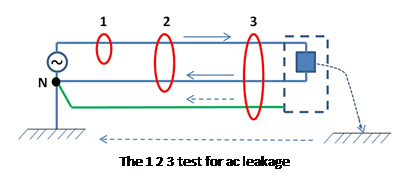 Kirchoff’s current law states that the sum of all currents flowing into and out of a node must equal zero. We can use this information to devise a test procedure for a dock. In the diagram below, the node we’ll use is marked “N.” Arrows with solid lines show where current should flow, and the dotted lines show where leakage can occur. Kirchoff’s current law states that the sum of all currents flowing into and out of a node must equal zero. We can use this information to devise a test procedure for a dock. In the diagram below, the node we’ll use is marked “N.” Arrows with solid lines show where current should flow, and the dotted lines show where leakage can occur.
If you want to measure the current flowing from the source to the load, you would place the clamp around a single conductor (1). But, using Kirchoff’s current law you can place the clamp around multiple conductors as shown at positions 2 and 3.
In a properly wired circuit, the clamp meter reading should be zero for positions 2 and 3. Any leakage current flowing in the green safety ground wire would be seen as a non-zero reading at position 2, and any leakage current from the load to earth would show a non-zero reading at positions 2 or 3.
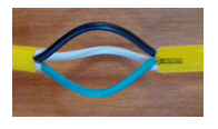
Since the green wire is included in the test at position 3, only the earth current, is registered as leakage in that case. I’ve made an accessory to allow convenient measurements in the three test positions shown in the diagram above. I bought a short extension cord and modified it as shown here to make the three conductors individually accessible.
You can read additional details in my original article here.
|