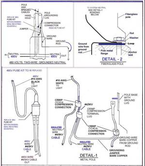
Grounding Myth No. 2 – Grounding Specifications for Street Lighting
Many of you have read my writing on Grounding versus Bonding and the frustration I have with those that fell that you need to make an installation safe from a ground fault is to 'drive a ground rod.'
Take a look at the following specifications for the grounding of "Street Light Betterment" (what does Betterment mean) for an unnamed City in Ohio.
Part III. INSTALLATION
 a. To Ground a Metal Pole - The bare ground wire shall be connected to the ground rod with a ground rod clamp. The ground wire shall be crimped to the terminal lug and bolted directly to the pole, and tightened with a nut and washer until secure. A jumper ground wire shall be crimped to the main ground wire and bonded to the #4 neutral by using a crimp connection. See Drawing 01S0131, "Detail 1".
Mike Holt Comment: I think the voltage in this detail must be wrong. I’m not aware of a 480V-to-ground system. I assume that it’s a 277/480V system, with 277V-to-ground.
b. To Ground a Fiberglass Pole - The bare ground wire shall be connected to the ground rod with a ground rod clamp. The ground wire shall be wrapped around an anchor bolt and tightened with the anchor nut and washer until secure. See Drawing 010S131 "Detail 2". Ground wire shall be crimped to the main ground wire and bonded to the #4 neutral by using a crimp.
Mike Holt’s Comment: Why on earth would you ground a fiberglass pole?
c. System Neutral - The white #10 wire shall run from the compression crimp of the #4 neutral through the pole shaft to the luminaire.
Mike Holt’s Comment: The termination of the grounding conductor from the ground rod to the neutral conductor violates the following NEC sections:
250.54 Auxiliary Grounding Electrodes. Auxiliary electrodes are permitted to be connected to the equipment grounding conductor. They need not be bonded to the building or structure grounding electrode system, the grounding conductor to the electrode need not be sized according to 250.66, and the contact resistance of the electrode to the earth is not required to comply with the 25 ohm requirement of 250.56.
The earth cannot be used as the effective ground-fault current path required by 250.4(A)(4).
250.142 Use of Neutral Conductor for Equipment Grounding.
(B) Load-Side Equipment. To prevent dangerous voltage on metal parts, the neutral conductor must not serve as an equipment grounding conductor on the load side of service equipment, except as permitted by 250.142(A).
Part IV. TESTING
a. Ground Test – Each ground rod shall be measured for earth resistance immediately after being upgraded. The earth resistance measurement shall not exceed 25 ohms. Ground rods or additional Ground rods shall be installed to achieve 25 ohms or less.
Mike Holt’s Comment: So the contractor is required to keep driving ground rods until the contact resistance is 25 ohms or less. What is the thinking here?
It amazes me that we have a grounding specifications for fiberglass light poles!
To quickly remove dangerous touch voltage on metal parts from a ground fault, the fault current path must have sufficiently low impedance to allow the fault current to quickly rise to a level that will open the branch-circuit overcurrent device. The fault current path must be capable of safely carrying the maximum ground-fault current likely to be imposed on it from any point on the wiring system where a ground fault may occur to the electrical supply source.
The earth is not considered suitable to serve as the required effective ground-fault current path.
Danger: Because the contact resistance of a ground rod (even at 25 ohms) is so great, very little fault current returns to the power supply if earth is the only fault current return path. Example: Ground fault current for a 277V ground fault to a 25 ohm ground rod would be only 11A (I = E/R, I = 277V/25 ohms).
Result—the circuit overcurrent device will not open and clear the ground fault and all metal parts associated with the electrical installation, metal piping, and structural building steel will become and remain energized by circuit voltage.