|
By Mike Holt
NEC® Consultant for EC&M Magazine
Do you understand the general requirements and the bonding requirements for solar installations?
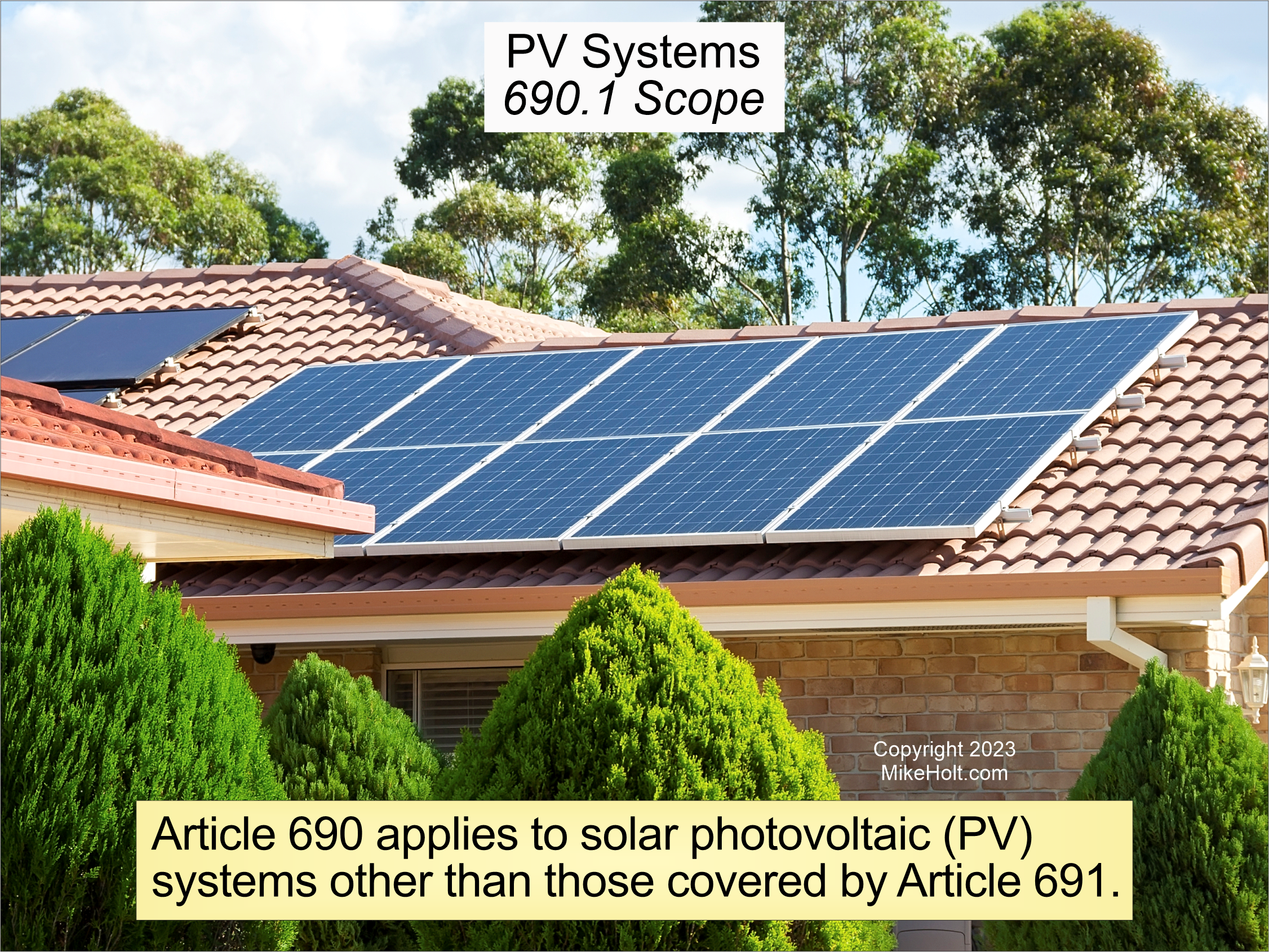
Figure 01
|
|
|
|
Figure 01
|
By Mike Holt
NEC® Consultant for EC&M Magazine
Note:
This article is based on the 2023 NEC.
Do you understand the general requirements and the bonding requirements for solar installations?
Article 690 covers solar installations, except large scale ones (those are covered in Article 691) [690.1].
Figure 01
Three important definitions:
- Photovoltaic (PV) System is the combination of components, circuits, and equipment up to and including the PV system disconnect, that converts solar energy into electrical energy [100].
- Inverter Generating Capacity is equal to the sum of parallel-connected inverter maximum continuous output power at 40°C in watts, kilowatts, volt-amperes, or kilovolt-amperes [100].
- PV Module is a unit of environmentally protected solar cells and components designed to produce dc power.
In Article 100, you'll find other important Article 690 terms, including AC Module, DC Combiner, DC-to-DC Converter, Electronic Power Converter, Functionally Grounded Inverter, Ground-Fault Detector-Interrupter, and Inverter Output Circuit.
General requirements
Components of the PV system including electronic power converters, inverters, PV modules, ac modules, ac module systems, dc combiners, dc-to-dc converters, PV rapid shutdown equipment, PV hazard control equipment, PV hazard control systems, dc circuit controllers, and charge controllers must be listed or they can be evaluated for the application and have a field label applied [690.4(B)].
Multiple PV systems are permitted on or in a building [690.4(D)]. But you cannot install PV system equipment and the PV system disconnecting means in a bathroom [690.4(E)].
Electronic power converters (inverters and dc-to-dc converters) don't need to be readily accessible, so they can be mounted on places such as roofs [690. 4(F)].
PV equipment floating on or attached to structures floating on bodies of water must be identified as being suitable for the purpose and have wiring methods that allow for expected movement of the equipment [690.4(G)]. PV equipment on bodies of water are subject to increased levels of humidity, corrosion, and mechanical and structural stresses. While the Code doesn't directly address these factors, account for them if you want a reliable installation.
The requirements of Article 690 do not apply to the PV source circuit conductors of an ac module [690.6(A)]. The ac output circuit conductors for an ac module are considered to be the inverter ac output circuit 690.6(B)].
Grounding and bonding
This topic leads to much confusion, but some clarity is achieved by looking at the definitions in Article 100. Grounding means you make a connection to the earth, and bonding means you make a connection to a low impedance metallic path.
An earth connection (ground) is for the supply (e.g., a separately derived source such as a transformer). The main purpose of grounding is to provide an alternate path for large transients such as lightning.
A low impedance connection (bond) is for the load (e.g., utilization equipment frames and enclosures). The main purpose of bonding is to remove dangerous voltage from metallic objects so undesired current cannot flow between them.
The earth is relatively high impedance when compared to the same length of copper wire, so it's not effective as a bonding means. This is why you never drive a ground rod next to a motor instead of connect a bonding jumper to it. Bonding creates a metallic path, even if that path is part of what is called the equipment grounding conductor. While the equipment grounding conductor ultimately connects to ground, it is in reality an equipment bonding conductor because it is connecting equipment to a low-impedance metallic path rather than connecting equipment to the earth.
Keep this short explanation in mind when applying any bonding or grounding requirements of the NEC.
PV system dc circuits must use one or more of the following system configurations: [690.41(A)]:
(1) 2-wire circuits with one functionally grounded conductor
(2) Bipolar circuits according to 690.7(C) with a functional ground reference (center tap)
(3) Circuits not isolated from the grounded inverter output circuit (functionally grounded inverter)
(4) Ungrounded circuits
(5) Solidly grounded circuits as permitted in 690.41(B)
(6) Circuits protected by equipment listed and identified for the use
Today's inverters are typically of the not isolated from the grounded inverter output circuit type [690.41(A)(3)]. These PV systems are known as functionally grounded inverters. A functionally grounded PV system is often connected to ground through an electronic means that is internal to an inverter or charge controller that provides ground-fault protection.
PV system dc circuits that exceed 30V or 8A must be provided with Ground-Fault Detector-Interrupter (GFDI) protection [690.41(B)]. If GFDI is not included in the dc-to-dc converter, the installation manual must provide a warning statement that indicates GFDI is not included.
The GFDI must provide three functions. The first is ground-fault detection. The GFDI device or system must be detect ground fault(s) in the PV system dc circuits, and be listed for providing GFDI protection. For dc-to-dc converters not listed as providing GFDI protection, where required, you must install listed GFDI protection equipment identified for the combination of the dc-to- dc converter and the GFDI device to protect the circuit.
The second is by controlling the faulted circuits in one of two ways:
(1) The current-carrying conductors of the faulted circuit must be automatically disconnected.
(2) The device providing GFDI protection fed by the faulted circuit must automatically cease to supply power to output circuits and interrupt the faulted PV system dc circuits from the ground reference in a functionally grounded system.
The third method is the GFDI equipment provides indication of ground faults at a readily accessible location.
Metal parts of PV module frames, PV equipment, and enclosures containing PV system ac and dc conductors must be connected to the circuit equipment grounding conductor per 690.43(A) through (D).
(A) Photovoltaic Module Mounting Systems and Devices. Devices used to secure and bond PV module frames to metal support structures and adjacent PV modules must be listed for bonding PV modules.
Note: UL 2703 is the Standard for Mounting Systems, Mounting Devices, Clamping/Retention Devices, and Ground Lugs for Use with Flat-Plate Photovoltaic Modules.
(B) Bonding Equipment to Metal Support Structure. Metal support structures listed, labeled, and identified for bonding and grounding metal parts of PV systems can be used to bond PV equipment to the metal support structure.
(C) Equipment Grounding Conductor Location. You can run equipment grounding conductors separately from the PV circuit conductor within the PV array. Where PV system circuit conductors leave the vicinity of the PV array, equipment grounding conductors must comply with 250.134.
(D) Bonding Over 250V. The bonding bushing and bonding jumper requirements contained in 250.97 for circuits over 250V to ground do not apply to metal raceways or metal cables containing PV system dc circuit conductors.
Equipment grounding conductors for PV system circuits must be sized per 250.122 based on the rating of the circuit overcurrent protective device [690.45].
Where no overcurrent protective device is required [690.9(A)(1)], the equipment grounding conductor for the PV system dc circuit must be sized per Table 250.122 based on an assumed overcurrent protective device for the circuit sized per 690.9(B). Equipment grounding conductors for PV system dc and ac circuits are not required to be increased in size to address voltage-drop considerations.
A building or structure supporting a PV system must have a grounding electrode system installed [690.47(A)]. PV systems are grounded when the PV inverter output ac circuit equipment grounding conductor terminates to the distribution equipment grounding conductor terminal [690.47(A)(1).
Most PV systems are functionally grounded rather than solidly grounded. A functionally grounded system is one that has an electrical ground reference (for operational purposes) that is not solidly grounded. It is often connected to ground through an electronic means that is internal to an inverter or charge controller that provides ground-fault protection.
Auxiliary grounding electrodes, per 250.54 can be connected to the PV module frame(s) or support structure [690.47(B)].
If an auxiliary electrode is installed, it is not required to be bonded to the building grounding electrode system, to have the grounding conductor sized to 250.66, or comply with the 25¦ single ground rod requirement of 250.53(A)(2) Ex [250.54].
Caution: An auxiliary electrode may cause PV system equipment failures by providing a path for lightning to travel through electronic equipment.
Source connections
Where a PV System operates in parallel with the electric utility as permitted by Article 705, a permanent plaque, label, or directory must be installed at the service disconnect location per 705.10 [690.56].
PV systems connected in parallel with the electric utility must have the interconnection made per Article 705 [690.59].
Coming up next
We've just covered the general requirements, grounding and bonding, and connection to other sources. These are Part I, V, and VI respectively of Article 690. In Part 2 of this series, we will cover the circuit requirements (Part II).
Learn more with Mike's Understanding NEC Requirements for Solar PV and Energy Storage Systems, or the Understanding the NEC
Complete Video Library:
|