|
|
| Free Resource - Conductor Sizing Spreadsheet for Parallel Applications | |
|
|
|
|
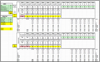
Explanation provided by the developer; Eric Stromberg, P.E.: I created this spreadsheet so I could see several combinations of conductors at the same time. I started with six columns and then ran into a situation where i needed eight, so I expanded the spreadsheet. I put the distance that these circuits could be run to stay within a voltage drop of 2% or 3%. Much of the software written gives a single answer for a given set of parameters. This spreadsheet allows the user to scan the different possibilities and make comparisons directly. The left eight columns give the minimum size of conductor combinations and the distances that these can be run. If these distances are not adequate, the user can select larger conductor sizes in the right set of columns to see how this affects the distance. If a conductor set chosen is smaller than allowed, the columns simply go blank. The voltage drop calculations are based on NEC Chap 9 Table 9. Note 2 contains the equation for Effective Z. This means of calculating voltage drop takes the magnetic qualities of the raceway into account, as well as the power factor. For motor starting applications, the power factor is generally assumed to be 40. Using a formula that does not consider power factor will often result in larger conductors than necessary. In the electrical industry, and on many electrical examinations, the “KID” formula is often used. The “KID” formula is described in the spreadsheet in the Cell Comments. I’ve included the 2% and 3% distances using the “KID” calculations for comparison. One of the things I learned from this spreadsheet is how dramatically power factor affects the distances of the different combinations. Pick a value of current such as 800, and look at the different allowable combinations available. Set the power factor to 100% and see how the distances decrease significantly as the number of conductors increase. Now set the power factor to 80 and watch the distances even out. There is a ‘notes’ tab on the spreadsheet that gives further explanations. The Green cells are the user inputs. Every other cell is an output. I didn’t protect the sheet so it may be a good idea to make a copy of it and store it somewhere in case one of the output cells is accidentally changed. Please feel free to give it a try, send me comments, and ask questions: Eric@MikeHolt.com Eric Stromberg, P.E. Los Alamos, New Mexico To access or download this free Conductor Sizing Spreadsheet for Parallel Applications, CLICK HERE or on the image above. Be sure to check out all the Free Resources available on our website: http://www.mikeholt.com/free-resources.php. |
|||
|
|
| Visit: Exam Preparation | Continuing Education | Code Products | Newsletters | and more | |||
|
|
|||
|

