PV Wire Sizing Program
Mike Holt Comment: I was recently contacted by Paul Dent with Koolbridge Inc. about a program he has written to assist with wire sizing for the PV source circuits and PV output circuit according to Article 690. He is providing this tool for free to the industry and you can access it by clicking here. Please be sure to read the message below from Paul and the instructions for how to use the program.
Message from Paul Dent: My company, Koolbridge Inc., was conceived to work on ways to reduce the installed cost of PV installations, big and small, to the point PV makes economic sense for everybody.
After 45 years working as an engineer, I am still a newbie to the electricians’ realm of the NEC, and I can appreciate the hassle and uncertainty that can arise in applying the Code, including the relatively new provisions of 690 for PV, which may still be unfamiliar. Therefore I have written a program to assist with this.
What the program does:
Enter your PV array parameters in the boxes provided as follows:
- Enter the module nameplate short circuit current Isc
- Enter the module nameplate maximum power point current Imp
- Enter the module nameplate maximum power point voltage Vmp
- Enter the number of strings that the combiner will parallel
- Enter the number of modules per string
- Enter the maximum outside ambient air temperature in degC for the location
- Enter the ambient temperature in degC for the location the combiner is installed
Note: The combiner is often installed in a cooler location (e.g. indoors) but may be installed in a hotter location than outside ambient, e.g. an attic. If installed outside in the shade, use same as outside ambient.
Note: If combiner function is provided by the inverter, use the inverter location.
- Select the distance the source circuit conduit is above the roof from the dropdown box for application of table 310.15(B)(3)(c)
- Select the terminal temperature limitation from the dropdown box as 60,75 or 90 degC according to the manufacturer's specification. If unspecified, use 75 degC.
- Enter the one-way run-length in feet for the PV source circuit (string) wiring from the furthest module to the combiner
- Enter the one-way run-length in feet for the PV output circuit wiring from the combiner to the load (i.e. inverter, battery or battery charge controller)
- Select the PV source circuit (string) wire gauge to try from the dropdown box
- Select the PV output circuit (combiner to load) wire gauge to try likewise
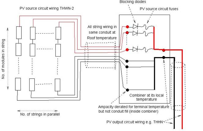
The program assumes the use of THWN-2 for the string wiring and THHN for the output circuit wiring and evaluates your trial gauges against all the known Code criteria and then highlights in red where your choice is inadequate, if any, so you can up the gauge and try again.
It checks voltage drop and applies the more severe criterion of < 2.5% that is typical for PV, but this is not a Code requirement. It also gives some hints where (source or output circuit wiring) the wire gauge is most economically upped if the total drop is too large or marginal.
There has been a lot of debate about the application of two areas of the code:
Terminal temperature limitations 690.8(B)(1)(b)
The position taken is that program derates the conductor ampacity by selecting the column of table 310.15(B)(16) according to the terminal temperature limit and then derates for ambient temperature
according to table 310.15(B)(2).
Then it checks that the derated ampacity meets both 690.8(B)(2)(b) AND that the conductor is protected at its derated ampacity by the selected PV output circuit fuse or other (OCPD).
Note: A PV output circuit fuse or other OCPD is not always required. It is required only if there is the possibility of backfeeding from a grid-tie inverter or battery. So ignore any warning that the terminal temperature ampacity of the PV output circuit conductors is too low for the fuse if there is no fuse or OCPD.
Standard fuse sizes for application of 240.4(B)
A conductor is protected by the fuse or OCPD as long as its derated ampacity is greater than the next standard fuse rating below the selected fuse. But 240.4(B) does not refer to the list of standard fuse sizes in 240.6(A). Meanwhile, 690.9(C) defines the standard fuse sizes for PV to be from 1 to 15 amps in steps of 1 amp and to be the values from 240.6(A) above 15 amps.
So for example, if your fuse is 15 amps and your conductor ampacity is 11,5 amps, the question is, does this meet 240.4(B) because the next standard size down from the list in 240.6(A) is 10 amps, or does it not meet 240.4(B) because the next standard fuse size down is 14 amps, according to 690.9(C) ?
After consultation with Mike Holt, it is agreed that, if an ampacity greater than 10A was safe for a 15A fuse BEFORE 690, then in can't suddenly be considered unsafe just because 690.9(C) allows a greater selection of fuse sizes. If it was now to be considered unsafe, then this would have to apply to non-PV systems too, which is not the intent!
Therefore the list of standard fuse sizes for application of 240.4(B) is limited to the list of 240.6(A).
I would appreciate any feedback or suggestions about how to improve the program to make it as useful as possible. Likewise suggestions for other areas that could benefit from some computer assistance are welcome. Feel free to comment or send me a private email at: paul.dent@att.net
