Basics of Surge and Transient Protection – Part 6
In this multipart series we will cover surge and transient protection for all types of signal, control and power lines. In Part 5 we looked at carbon block and spark (air) gap devices. In this segment we will look at gas discharge tubes.


Figure 1 Two and Three Terminal GDTs
Gas discharge tubes (GDT) have two or three metal electrodes inside a sealed glass or ceramic envelope. The envelope is filled with typically neon or argon gas. At room temperatures and with no applied voltage, the tube has nearly infinite resistance. However, once a certain threshold voltage is exceeded (this voltage depends on the gas pressure and geometry of the lamp), the gas ionizes (turns into plasma) and the resistance between the elements drops to a near short. Because there is a very low voltage across the tube very little energy is dissipated in the tube. Current will continue to flow through the tube until the current drops below the current required to maintain ionization of the gas. On an AC circuit the zero crossing is frequently sufficient to allow the tube to drop out of conduction restoring normal circuit operation. However, if the electrodes are still too warm and the gas remains ionized the arc may reinitiate during the next half cycle. If the normal power source is sufficient this follow on current may damage the electrodes. Techniques for solving this problem include placing a current limiting resistor, or small value clamping device in series with the gas tube. Gas tubes can also be selected with a high follow on current threshold.
Gas tubes are frequently used to protect Telecom circuits where their low shunt capacitance is a desirable characteristic. When a three terminal gas tube is used to protect a TELCO signal pair a transient on either wire of the pair will cause the gas to ionize and short both lines to the grounded center terminal. This provides both line to line and line to ground protection. It is interesting that when speaking of surges the telecom community utilizes different terms from the rest of the electronics industry. Most electronic engineers refer to line to ground surges as common mode and line to line as differential mode protection. Telecom engineers refer to the common mode surge as a longitudinal or tip and ring to ground surge and a differential mode surge as a metallic or tip to ring surge.
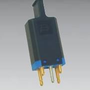
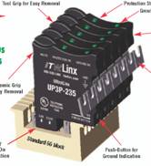
The high current capability relative to the size of the GDT allows for convenient packaging. Three popular options are the five pin protector, 66 block protector, and 110 block protector as shown in figure 2. These protectors may contain both gas tubes and/or solid state protector elements. When GDTs are combined with other stages of protection it is said to be hybrid protection. We will discuss hybrid protection circuits in a later segment.


Figure 2 Telecom Protector Options
GDTs suffer from several drawbacks, as we previously mentioned there is a tendency to have follow on current even in an AC circuit, the time required to initiate conduction is far greater than the time required to overcome junction delay in a solid state device, and finally the turn on voltage may vary over the life of the GDT. The negative impact of some of these characteristics can be minimized by combining a GDT with solid state stages in hybrid circuits.
Next segment we will look at some of the more sophisticated and solid state types of crowbar devices. Examples of these include silicon controlled rectifiers (SCR), Sidactors, Thyristors, and Surgectors.
Copyright © 2005 by E. F. Roberts and Assoc., www.efrobertsassoc.com
Ed Roberts, ed.roberts@efrobertsassoc.com
Lightning and Transient Protection, Grounding, Bonding and Shielding Education