|
By Mike Holt
NEC® Consultant for EC&M Magazine
If you missed Parts 1 and 2 click here.
Note: This article is based on the 2023
NEC.
Disconnecting means and wiring methods for solar installations must meet requirements specific to solar photovoltaic systems.
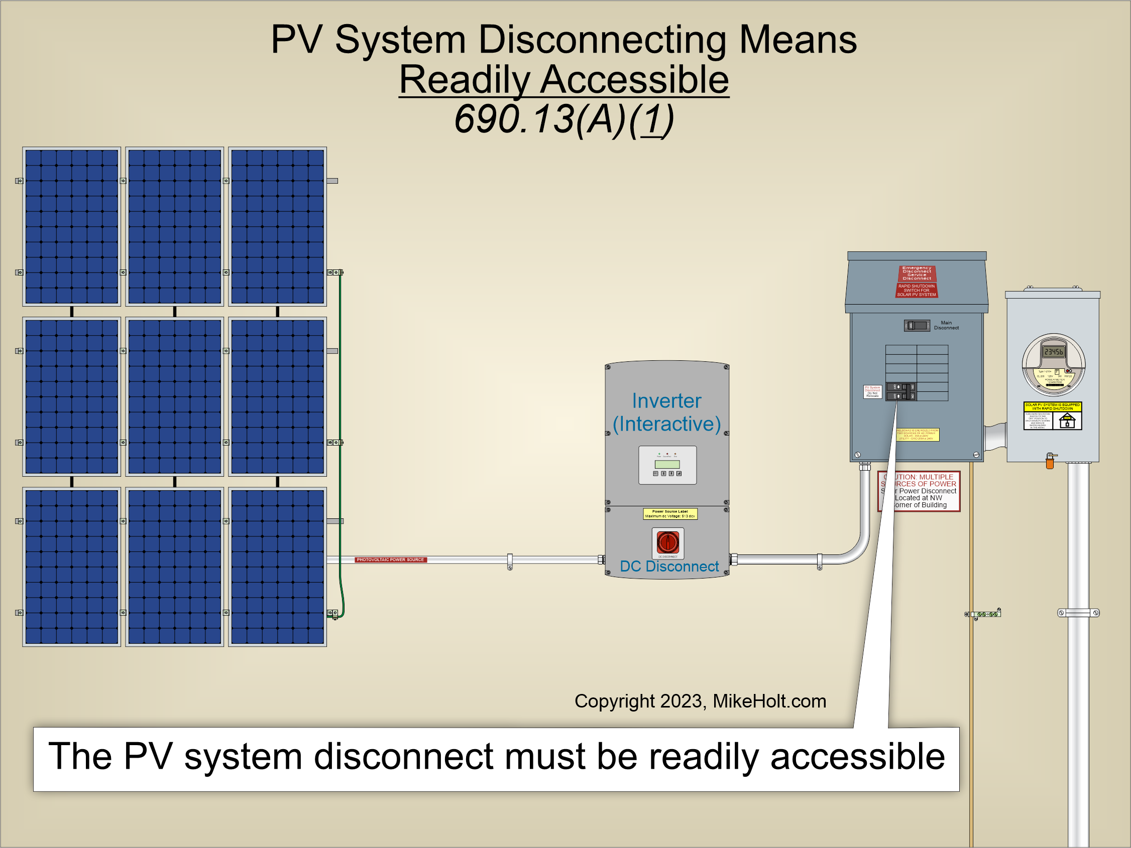
Figure 01
|
|
|
|
Figure 01
|
By Mike Holt
NEC® Consultant for EC&M Magazine
If you misseds Part 1 and 2 click here.
Note:
This article is based on the 2023 NEC.
Disconnecting means and wiring methods for solar installations must meet requirements specific to solar photovoltaic systems.
A readily accessible disconnecting means is required to disconnect power from each PV system [690.13(A)(1)].
Figure 01
The door or hinged cover for the PV system disconnect must be locked or require a tool to open [690.13(A)(2)]. The PV system disconnect must indicate if it is in the open (off) or closed (on) position and must be marked PV SYSTEM DISCONNECT or equivalent [690.13(B)].
Where the line and load terminals of the PV system disconnect may be energized when the disconnect is in the open (off) position, the disconnect must be marked with an electric shock warning [690.13(B)]. The warning markings on the disconnect must be permanently affixed and have sufficient durability to withstand the environment involved [110.21(B)].
The disconnecting means for each PV system must:
- Consist of not more than six switches and/or six sets of circuit breakers [690.13(C)]. A single PV system disconnect is permitted for the combined ac output of one or more microinverters or ac modules. But this requirement of a maximum of six PV system disconnects does not limit the number of PV systems on a premises.
- Be rated for the circuit current, the available fault current, and voltage [690.13(D)].
- Be capable of being locked i the open position per 110.25 [690.13(E)].
- Be one of the five types listed in 690.13(E). For example, a pull-out switch with sufficient interrupting rating.
Equipment isolating device
An equipment disconnect or isolating device must be provided for ac PV modules, fuses, dc-to-dc converters, and inverters. It must meet the four requirements of 690.15(A) through (D). For example, it can be a disconnect per 690.15(C). With the 2023 revision, these requirements have been extensively rewritten. Pay particular attention to where these can be located and how they can be controlled [690.15(D)].
Wiring methods
Where wiring devices with integral enclosures are used, a sufficient length of cable must be provided to facilitate replacement [690.31(A)(1)]. PV system dc circuit conductors operating at over 30V that are readily accessible to unqualified persons must be guarded, or installed within a raceway, in multiconductor jacketed cable, or Type MC cable [690.31(A)(2)].
PV circuit conductors with insulation rated at 105°C and 125°C can have their ampacities determined per Table 690.31(A)(3)(1) and corrected per Table 690.31(A)(3)(2) [690.31(A)(3)]. Wiring systems specifically listed for PV systems are permitted [690.31(A)(4)].
PV system dc circuit conductors can be installed in the same enclosure, cable, or raceway with other PV system dc circuit conductors, unless prohibited by equipment listing [690.31(B)(1)].
But PV system dc circuit conductors cannot be installed in the same enclosure, cable, or raceway with inverter ac output circuit conductors or other conductors unless separated by a barrier or partition.
Ex. Where all conductors or cables have an insulation rating equal to at least the maximum circuit voltage applied to any conductor, then:
(1) Multiconductor jacketed ac cables can be in the same enclosure with dc circuits where all circuits serve the PV system.
(2) Inverter output ac circuits can be in the same enclosure or wireway with PV system dc circuits that are identified and grouped per 690.31(B)(2) and (B)(3).
(3) Multiconductor jacketed cable, Type MC cable, or listed wiring harnesses identified for the application can be in the same enclosure or raceway with non-PV system circuits.
PV system dc circuit conductors must have all termination, connection, and splice points permanently identified for polarity by color coding, marking tape, tagging, or per 690.31(B)(2)(a) and (B)(2)(b) [690.31(B)(2)].
PV system dc and ac conductors in the same enclosure or wireway must be grouped separately with cable ties or similar means at least once and at intervals not to exceed 6 ft [690.31(B)(3)].
Ex: Grouping is not required if the dc circuit enters from a cable or raceway unique to the circuit that makes the grouping obvious.
Single conductor cables for PV systems must comply with 690.31(C)(1)(a) through (C)(1)(c). For example, exposed cables 8 AWG or smaller must be supported and secured at intervals not to exceed 24 in. Use cable ties, straps, hangers, or similar fittings listed and identified for securement and support in outdoor locations.
Single-conductor Type PV wire, Type PV cable, or Type DG cable can be installed in cable trays in outdoor locations [690.31(C)(2)].
Where installed in uncovered cable trays, the ampacity of single-conductor PV wire smaller than 1/0 AWG and the adjustment factors for 1/0 AWG single-conductor cables in 392.80(A)(2) can be used.
Where single-conductor PV wire smaller than 1/0 AWG is installed in ladder ventilated trough cable trays, the following apply:
(1) All single conductors must be installed in a single layer.
(2) Conductors that are bound together to comprise each circuit pair can be installed in other than a single layer.
(3) The sum of the diameters of all single-conductor cables must not exceed the cable tray width.
Flexible cords connected to moving parts of tracking PV arrays must be installed per Article 400, be identified as hard-service cord or portable power cable, be suitable for extra-hard usage, and be listed for outdoor use, water resistant, and sunlight resistant [690.31(C)(4)].
Flexible, finely-stranded cables must terminate on terminals, lugs, devices, or connectors identified for the use of finely stranded conductors per 110.14 [690.31(C)(5)].
Wiring methods for PV system dc circuits on or in buildings must comply with several additional requirements [690.31(D)]. For example, PV system dc circuit conductors inside a building must be installed in a metal raceway, Type MC cable that complies with 250.118(A)(10)(b), and metal enclosures.
Ex: PV hazard control system conductors that are installed for a rapid shutdown application per 690.12(B)(2)(1) can be provided with (or listed for use with) nonmetallic enclosures, nonmetallic raceways, and nonmetallic cables at the point of penetration of the building.
Roof-mounted PV array mounting systems can be held in place with an approved means other than those required by 110.13 and must utilize wiring methods that allow for any expected movement of the array [690.31(F)]. Expected movement of unattached PV arrays is often included in structural calculations.
PV system dc circuits greater than 1000V are not permitted on or in one- and two-family dwellings, or within buildings containing habitable rooms [690.31(G)]. They must be located less than 10 ft above grade on the exterior of buildings, and cannot be attached to the building surface for more than 33 ft from the equipment.
Fittings and connectors for PV systems with concealed wiring methods must be listed for the on-site interconnection of modules or other array components [690.32]. Building-integrated PV systems are a part of the buildings structure and have PV system dc circuit conductors concealed by built-up, laminate, or membrane roofing materials as well as solar shingle and facade systems.
Mating connectors, other than listed connectors for building-integrated PV systems as covered in 690.32, must comply with the following [690.33]:
(A) Configuration. Mating connectors must be polarized and be noninterchangeable with other electrical systems on the premises.
(B) Guarding. Mating connectors must be constructed and installed to guard against inadvertent contact with live parts by persons.
(C) Type. Mating connectors must be of the latching or locking type and, where readily accessible, require a tool for opening. Where mating connectors are not of the identical type and brand, they must be listed and identified for intermatability as described in the manufacturer's instructions.
(D) Interruption of Circuit. Mating connectors must comply with one of the following requirements.
(1) Mating connectors must be rated to interrupt the current without hazard to the operator.
(2) A tool must be required to open the mating connector, and the mating connectors must be marked DO NOT DISCONNECT UNDER LOAD or NOT FOR CURRENT INTERRUPTING.
(3) Mating connectors supplied as part of listed equipment must be used per instructions provided with the listed connected equipment.
Some listed equipment, such as micro-inverters, are evaluated to make use of mating connectors as disconnect devices even though the mating connectors are marked as DO NOT DISCONNECT UNDER LOAD or NOT FOR CURRENT INTERRUPTING.
The NEC allows you to locate junction, pull, and outlet boxes behind PV modules [690.34].
Avoiding problems
Before engineering the interconnection of PV system components, remember there are special requirements for disconnects and wiring methods for these systems. Choose your disconnects, raceway, fittings, wiring, and connectors only after a thorough review of Parts III and IV of Article 690.
Learn more with Mike's Understanding NEC Requirements for Solar PV and Energy Storage Systems:
|