|
By Mike Holt
NEC® Consultant for EC&M Magazine
If you missed Part 1, click here
Note: This article is based on the 2023
NEC.
Do you know the rules for service entrance conductors and service disconnects?
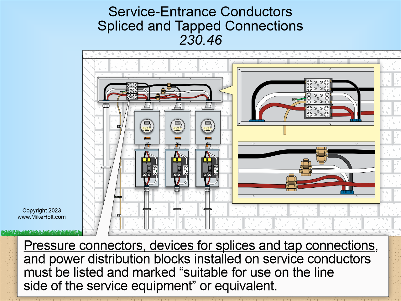
Figure 01
|
|
|
|
Figure 01
|
By Mike Holt
NEC® Consultant for EC&M Magazine
If you missed Part 1, click here.
Note:
This article is based on the 2023 NEC.
Do you know the rules for service entrance conductors and service disconnects?
Service entrance conductors differ from service conductors. They are the conductors between the terminals of the service equipment and the service drop, overhead service conductors, service lateral, or underground service conductors [100]. By contrast, service conductors run from the service point to the service disconnect [100].
Each service drop, service lateral, or set of underground or overhead service conductors can supply only one set of service-entrance conductors [230.40]. There are five exceptions. For example, Ex 2: Service-entrance conductors can supply two to six service disconnects per 230.71(B).
Service conductors must have an ampacity of at least the largest of the calculations in 230.42(A)(1) or (2) [230.42]. For example, service conductors must have an ampacity of at least 125 percent of the continuous loads, plus 100 percent of the noncontinuous loads, based on the temperature rating of equipment per 110.14(C)(1) and Table 310.16, prior to conductor ampacity correction and/or adjustment [230.42(A)(1)].
The service neutral conductor must have an ampacity to carry the maximum unbalanced load per 220.61 and not be smaller than required by 250.24(D) [230.42(C)].
Service-entrance conductors can be installed with any of the twenty-one wiring methods listed in 230.43. For example, wireways, EMT, and MC cable.
Pressure connectors, devices for splices and tap connections, and power distribution blocks installed on service conductors must be listed and marked suitable for use on the line side of the service equipment or equivalent [230.46]. Figure 01
You must protect service-entrance cables that are subject to physical damage, using one of the 6 methods listed in 230.50(B)(1) through (6). For example, use EMT.
Service-entrance cable must be supported within 1 ft of the weatherhead, gooseneck, raceway connections, or enclosure. Supports must be at intervals not exceeding 30 in [230.51(A)].
Service weatherheads on raceways or service-entrance cables must be above the point of attachment [230.26] for service-drop or overhead service conductors [230.51(C)].
Ex: If it is impractical to locate the service head above the point of attachment, it must be within 2 ft of the point of attachment.
Drip loop conductors must be connected to the service-drop or overhead service conductors below the service head or termination of the service-entrance cable sheath [230.51(F)].
On a 4-wire, delta-connected, three-phase high-leg system, the conductor with the higher phase voltage-to-ground (208V high-leg) must be durably and permanently marked by an orange outer finish or other effective means [230.56]. Such identification must be placed at each point on the system where both a connection is made and the neutral conductor is present [110.15].
Surge protection
Where a service supplies any of the following occupancies, you must provide a surge-protective device [230.67(A)]:
(1) Dwelling units.
(2) Dormitory units.
(3) Guest rooms and guest suites of hotels and motels.
(4) Areas of nursing homes and limited care facilities used exclusively as patient sleeping rooms.
The surge-protective device must be a Type 1 or Type 2 SPD [230.67(C)] and must be an integral part of the service disconnect or be immediately adjacent to the service disconnect [230.67(B)]. Ex: The surge-protective device is permitted to be at the downstream panelboard.
Service disconnect
The service disconnect must be marked to identify it as suitable for use as service equipment and must be permanently marked to identify it as a service disconnect [230.66(A)].
The service disconnect must open all phase conductors [230.70]. It must be placed at a readily accessible location either outside the building or inside nearest the point of service conductor entry [230.70(A)(1)].
Each service must have only one service disconnect except as permitted in 230.71(B). Each service can have up to six service disconnects per 230.71(B)(1) through (5). For example, panelboards with a service disconnect in each panelboard.
The service disconnects for each service must be grouped and marked to indicate the load served [230.72(A)].
To minimize the possibility of simultaneous interruption of power, the disconnect for fire pumps [Article 695], emergency systems [Article 700], legally required standby systems [Article 701], or optional standby systems [Article 702] must be remote from the service disconnect(s) for normal service [230.72(B)].
The service disconnect for a building must have an ampere rating of at least the calculated load per Article 220, and in no case can it be less than the values listed in 230.79(A) through (D). For example, for installations consisting of two 2-wire branch circuits, the disconnect must have an ampere rating of at least 30A.
Only eleven types of electrical equipment can be connected to the supply side of the service disconnect [230.82]. For example:
- Cable limiters.
- Meters and meter sockets rated at least 1000V.
- Type 1 SPDs.
- Emergency disconnects for one- and two-family dwelling units.
Emergency disconnect
For one- and two-family dwelling units, an emergency disconnect must be installed per 230.85(A) through (E).
(A) General. The requirements are about what you'd expect: readily accessible, within sight from the dwelling unit, has a short-circuit rating at least that of the available fault current, and grouped if more than one disconnect.
(B) Type. It has to be a service disconnect, integrated meter disconnect, or other listed switch or circuit breaker suitable for service equipment.
(C) Replacement. Where a service disconnect is replaced, all the requirements of this section apply.
(D) Identification. Where disconnects for other energy source systems are not adjacent to the emergency disconnect, a plaque or directory identifying the location of all other energy source disconnects must be adjacent to the emergency disconnect.
(E) Marking. There are five marking requirements. For example, the marking or labels must be on the outside front of the disconnect with a red background and white text.
Service conductor overcurrent protection
Each service phase conductor must have overload protection [230.90].
The service overcurrent protective device provides overload protection for the line side of service conductors, but not short-circuit and ground-fault protection because that protection can be provided only at the supply end of a circuit.
The rating of the overcurrent protective device must not be greater than the ampacity of the service phase conductors [230.90(A)].
Ex 2: If the ampacity of the phase conductors does not correspond with the standard rating of overcurrent protective devices as listed in 240.6(A), the next higher overcurrent protective device can be used if it does not exceed 800A [240.4(B)].
Ex 3: The combined ratings of two to six service disconnects can exceed the ampacity of the service conductors only if the calculated load does not exceed the ampacity of the service conductors per Article 220.
Ex 5: Overload protection for dwelling unit services is permitted per the requirements of 310.12.
The service disconnect fuse or circuit breaker supplies overload protection, but not short-circuit and ground-fault protection, for the line-side service conductors.
The service grounded conductor can terminate on a circuit breaker that simultaneously opens all conductors of the circuit [230.90(B)]. A breaker so configured is the only overcurrent device that can be inserted into a grounded service conductor.
The service overcurrent protective device must be an integral part of the service disconnect or be immediately adjacent to the service disconnect [230.91]. Where fuses are used as the service overcurrent protective device, the disconnect must be ahead of the supply side of the fuses.
Each service disconnect rated 1000A or more supplied by a 4-wire, three-phase, 277/480V wye-connected system must be provided with ground-fault protection of equipment [230.95]. The rating of the service disconnect is based on the rating of the largest fuse that can be installed or the circuit breaker's highest continuous current trip setting.
Code compliant services
Article 230 is one of the larger articles in the Code. It's also complex, with many rules that can be hard to check at the drawing desk or in the field. This fact has not gone unnoticed by Code-Making Panel Number 10 (the CMP responsible for Article 230). For many Code cycles now, Figure 230.1 has provided both a list and a graphic that show you how Article 230 is laid out.
You can see at a glance that if you're working with overhead conductors you need to refer to Part II but if those conductors are underground you need to refer to Part III. So look at this table to identify which Part in Article 230 matches where you are in your design workflow or installation process.
Don't confuse service conductors (Parts II and III) with service-entrance conductors, either.
Learn more with Mike's Understanding the NEC
Complete Library:
|