Basics of Surge and Transient Protection – Part 7
In this multipart series we will cover surge and transient protection for all types of signal, control and power lines. In Part 6 we looked at gas discharge tubes. In this segment we will look at the more sophisticated and solid state types of crowbar devices. Examples of these include silicon controlled rectifiers (SCR), and thyristors.
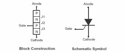
SCR’s are three terminal P-N-P-N crowbar type devices. The three terminals, as shown in Figure 1. SCR Construction, are the cathode, anode and gate. The device is turned on by a momentary positive pulse at the gate terminal. The circuit remains “on” until it is “turned off” by reducing the anode-to-cathode current below a threshold known as the holding current of the SCR. A circuit is required to develop the trigger required to induce conduction for an SCR to be employed as a surge protective device.

Figure 1. SCR Construction
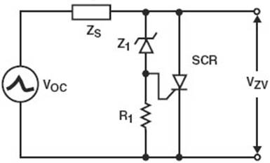
The most common means of developing this trigger pulse to trigger the SCR into conduction is illustrated in Figure 2. Triggered SCRwhere a silicon avalanche diode (SAD) Z1 is used to provide initial clamping before turn on of the SCR due to the voltage rise developed across resistor R1..

Figure 2 . Triggered SCR
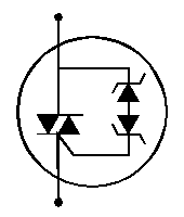
Semiconductor thyristors used for surge protection similar to those shown in Figure 3 are marketed under trade names such as SIDACtor/Surgector (Littelfuse), TISP (Bourns), Trisil (STMicroelectronics) and SiBar (Raychem).
A triggered thyristor performs overvoltage protection by acting as a switch, shunting the surge currents away from the protected circuit, while clamping the induced transient voltages. While the voltage across the thyristor is below its Off-state voltage, VDRM, it remains in a high-impedance state. As the voltage approaches VDRM, it exhibits characteristics similar to a silicon avalanche diode (SAD). When the current reaches a value, IS, the thyristor switches to the On-state and conducts current at a voltage of VT. If the maximum surge current of the thyristor is greatly exceeded, it enters a state of permanent conduction and will not return to its high-impedance Off-state.

Figure 3 . Bi-directional Triggered Solid State Thyristor
These types of triggered crowbars provide rapid clamping through the trigger circuit and a bulk crowbar device capable of handling significant amounts of power. These devices thus combine some of the best characteristics of SADs and gas tubes. They are frequently employed in telecom protective circuitry and are sometimes employed in so called five pin protectors. More data about specific device characteristics are available on the suppliers’ websites listed below. These components are employed in various protection manufacturers’ protective devices.
www.circuitprotection.com/sibar.asp
www.ortodoxism.ro/datasheets/stmicroelectronics/5015.pdf
www.littelfuse.com/data/en/Product_Catalogs/ Chapter1SIDACtorProductSelectionGuide.pdf
www.bourns.com/cat.aspx?C=1
Next segment we will look at some of the feedback that has been received concerning this series. I will try to answer any questions received by the end of this month either on this website or sent to ed.roberts@efrobertsassoc.com .
Ed Roberts
ed.roberts@efrobertsassoc.com
Lightning and Transient Protection, Grounding,
Bonding and Shielding Education
www.efrobertsassoc.com
Copyright © 2005 by E. F. Roberts and Assoc.