This article was posted 08/08/2007 and is most likely outdated.

Grounding Myth No. 2 – Grounding Specifications for Street Lighting


Topic - Grounding versus Bonding
Subject - Grounding Myth No. 2 – Grounding Specifications for Street Lighting

August 8, 2007
This newsletter was sent to 25564 newsletter subscribers

Ask a Question |  Weekly Code GraphicQuizzes |  Free Stuff InstructorsOnline Training Products | Seminars | SubscribeUnsubscribe
[ image1 Post Comments | View Comments | Notify Me When Comments Are Added ] Web Page Version [Printer-Friendly]    

Grounding Myth No. 2 – Grounding Specifications for Street Lighting


Many of you have read my writing on Grounding versus Bonding and the frustration I have with those that fell that you need to make an installation safe from a ground fault is to 'drive a ground rod.'


Take a look at the following specifications for the grounding of "Street Light Betterment" (what does Betterment mean) for an unnamed City in Ohio.


Part III. INSTALLATION


Image
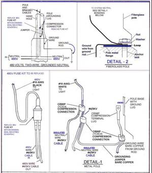
a. To Ground a Metal Pole - The bare ground wire shall be connected to the ground rod with a ground rod clamp. The ground wire shall be crimped to the terminal lug and bolted directly to the pole, and tightened with a nut and washer until secure. A jumper ground wire shall be crimped to the main ground wire and bonded to the #4 neutral by using a crimp connection. See Drawing 01S0131, "Detail 1".


Mike Holt Comment: I think the voltage in this detail must be wrong. I’m not aware of a 480V-to-ground system. I assume that it’s a 277/480V system, with 277V-to-ground.


b. To Ground a Fiberglass Pole - The bare ground wire shall be connected to the ground rod with a ground rod clamp. The ground wire shall be wrapped around an anchor bolt and tightened with the anchor nut and washer until secure. See Drawing 010S131 "Detail 2". Ground wire shall be crimped to the main ground wire and bonded to the #4 neutral by using a crimp.


Mike Holt’s Comment: Why on earth would you ground a fiberglass pole?


c. System Neutral - The white #10 wire shall run from the compression crimp of the #4 neutral through the pole shaft to the luminaire.


Mike Holt’s Comment: The termination of the grounding conductor from the ground rod to the neutral conductor violates the following NEC sections:

250.54 Auxiliary Grounding Electrodes. Auxiliary electrodes are permitted to be connected to the equipment grounding conductor. They need not be bonded to the building or structure grounding electrode system, the grounding conductor to the electrode need not be sized according to 250.66, and the contact resistance of the electrode to the earth is not required to comply with the 25 ohm requirement of 250.56.

Author’s Comments: Typically, an auxiliary electrode (what the 2008 will call the supplementary  electrode) serves no useful purpose.

The earth cannot be used as the effective ground-fault current path required by 250.4(A)(4).

Author’s Comment: Because the contact resistance of a grounding electrode to the earth is high, very little ground-fault current returns to the electrical supply source via the earth. The result is the circuit overcurrent device will not open and clear a ground fault; therefore, metal parts will remain energized with dangerous potential.

250.142 Use of Neutral Conductor for Equipment Grounding.

Author’s Comment: To remove dangerous voltage on metal parts from a ground fault, the metal parts of electrical raceways, cables, enclosures, and equipment must be connected to an equipment grounding conductor of a type specified in 250.118 in accordance with 250.4(A)(3).

(B) Load-Side Equipment. To prevent dangerous voltage on metal parts, the neutral conductor must not serve as an equipment grounding conductor on the load side of service equipment, except as permitted by 250.142(A).


Part IV. TESTING


a. Ground Test – Each ground rod shall be measured for earth resistance immediately after being upgraded. The earth resistance measurement shall not exceed 25 ohms. Ground rods or additional Ground rods shall be installed to achieve 25 ohms or less.


Mike Holt’s Comment: So the contractor is required to keep driving ground rods until the contact resistance is 25 ohms or less. What is the thinking here?


It amazes me that we have a grounding specifications for fiberglass light poles!


To quickly remove dangerous touch voltage on metal parts from a ground fault, the fault current path must have sufficiently low impedance to allow the fault current to quickly rise to a level that will open the branch-circuit overcurrent device. The fault current path must be capable of safely carrying the maximum ground-fault current likely to be imposed on it from any point on the wiring system where a ground fault may occur to the electrical supply source.


The earth is not considered suitable to serve as the required effective ground-fault current path.

Danger: Because the contact resistance of a ground rod (even at 25 ohms) is so great, very little fault current returns to the power supply if earth is the only fault current return path. Example: Ground fault current for a 277V ground fault to a 25 ohm ground rod would be only 11A (I = E/R, I = 277V/25 ohms).

Result—the circuit overcurrent device will not open and clear the ground fault and all metal parts associated with the electrical installation, metal piping, and structural building steel will become and remain energized by circuit voltage.

Click here to post a comment
[ View More Newsletters ] [ Send to a Friend ] [ Post Comments | View Comments | Notify Me When Comments Are Added ]

Copyright © Mike Holt Enterprises, Inc. All rights reserved.
This article is protected by United States copyright and other intellectual property laws and may not be
displayed or published on the internet without the prior written permission of Mike Holt Enterprises, Inc.

http://www.MikeHolt.com     1-888-NEC-CODE (1-888-632-2633)

Experiencing a Problem? Click Here

 
Comments
  • Grounding rods vs preaching they serve no purpose. . .

    Electricty does strange things in its multiple routes to ground. Every path and instance of injury or damage cannot be perfectly explained. We can make farily accurate assumptions based on our understanding of electricty, but the power is disconnected before rescue and repairs are take place.

    Is is possible that a shorted ballast in the fixture might energize a rain soaked pole and a grounding rod dissapate enough of the voltage to protect life. Maybe . . . Maybe not in a perfect situation. Does having a requirement to ground a fiberglass pole create a problem?

    As far as grounding helping to save equipment, the following description of events are very real and accuratly described:

    On Jan 6, 2002, Okaloosa County traffic signal technicians were called to make emergency repairs to the intersection of US98 @ Beach Drive. A power line had fallen across the mast arm located on the NE corner of the intersection.

    By the time signal technicians arrived, the power line had been repaired but there was extensive damage to the intersection. The poly signal assemblies were actually blown apart and completely destroyed. The intersection’s signal cabinet (which was located on the opposite side of a the six lane divided highway), electronic equipment, and wiring were badly damaged. All damage was directly caused by the power line’s contact with the mast arm, which took every available path to ground.

    The signal pole that was struck recent modifications and the pole’s grounding wire was removed from the intersections grounding system (all poles are supposed to be connected to grounding rods which are all bonded with #6 wire).

    The intersection was repaired and the pole was connected to the grounding system.

    In a freak coincidence, the power line fell again on Feb 27, 2002 in the same spot as the downed power line of Jan 6, 2002. This time, the mast arm was grounded. Within inches of the power line's contact with the arm, new equipment had been installed that enables emergency vehicles to activate signal changes.

    There was damage to the intersection, but it was much less. The signal housings and lenses were not badly damaged (Approximately 8 lamps burnt out). Newly installed emergency vehicle equipment was not damaged. The signal wiring was not burnt. The microprocessor was not damaged.

    The intersection was placed back into operation within minutes after a survey of damages.

    Why does having a requirement for grounding create such a problem? If an educated person of reasonably sound mind has the authority to include grounding in the specification and the installers do not follow the specification . . . fire them. If they wish to debate the spec that might be a different issue for discussion, but what is "dangerous" is simply ignoring specs.

    Al Poudrier

Reply to this comment
* Your Name:
   Your name will appear under your comments.

* Your Email:
   Your email address is not displayed.
* Comments:

Email Notification Options:
Notify me when a reply is posted to this comment
Notify me whenever a comment is posted to this newsletter