An analogy for three phase current flow
by Eric Stromberg, P.E.
An attendee of a seminar that Mike Holt held in Puerto Rico asked the following question:
Q: I don't want to be a bother, but I'm looking for the explanation of an age long notion in my industry, PREPA (Puerto Rico Electric Power Authority). The people in charge of the distribution standards here indicate that the neutral or common line can be smaller than the live lines. The revelations during your seminar here got me thinking about stuff like that, which I always felt was wrong. The gauge chosen for the neutral is usually half that of the other lines, and I say this is wrong because at any given moment it may carry the same amount of current as the line.
In your first answer you stated that if all phases carry the same current, the neutral current will be zero...how? I understand this if the load is purely 3 phase, there's no use of the neutral. But for line-neutral loads, how? And I don't mean mathematically, I mean, what's happening with the flow of current there?
A: Julio. You've given me a significant challenge with your statement "and I don't mean mathematically." Effectively, if the currents are balanced on each phase, they add up to zero on the Neutral. Think of a single phase 120/240 Volt system. If 'phase' A has 20 Amps on it and 'phase' B has 0 Amps on it, the Neutral has 20 Amps on it. If both 'phases' have 20 Amps on them, the Neutral has zero Amps. If 'phase' A has 20 Amps on it and 'phase' B has 10 Amps on it, then the Neutral has 10 Amps on it. The Neutral carries the imbalance current of the ungrounded conductors.
OK, we're going to try to do this totally non-mathematically. After typing that last sentence, however, I've been sitting here thinking of exactly how to describe this without mathematics. Trouble is, mathematics is the best way to describe it. The "adding up to zero" is a convenient mathematical construct that has no real world analogy. This is because the voltages are time-shifted. Our brains don't think like this. Try to imagine three garden hoses, each at the point of an equilateral triangle, spraying water into a single point. Now, imagine that each hose is alternately spraying water and then 'sucking' water back, according to a specified frequency. If all the hoses are spraying/sucking water, but are time shifted between them, it turns out that whatever water is being sprayed into the center (at any given time) is also being sucked up by the other hoses. As long as each hose is spraying/sucking the same volume of water, there is no residual water laying on the ground. If, however, the hoses are not spraying/sucking the same volume of water, an amount of water will be deposited on the ground. This is the 'imbalance' water that returns to the source via a different path.
Julio, you are absolutely correct in that, if only phase A (or B, or C) loads are present, then the full current of phase A will also be present on the Neutral. If full current is present on two phases, then full current is present on the Neutral.
I'm not sure if any of this helps. It is a difficult concept that takes some time to figure out.
Q: OK Eric, I made a drawing and thought about what you explained. My main issue is if the Neutral current might be zero or near zero, then how multiple, unbalanced, line-neutral loads work?
If I understand correctly what you explained, there is a sharing of current between the lines, consequently, at a given time, 2 loads might be sharing current from a different phase. For example, there's a load in A-N and another in B-N, at a given time both loads will have an A-B current; depending on the system, it could be A-C and B-C on each load. Is this thinking correct?
If so, that makes clear why the Neutral current is usually low or may reach zero, and indeed your analogy is an excellent one. A new question would be, why is that path used instead of the lower resistance path of the neutral?
A: You’re right. This where my analogy falls short. Let me change my analogy from hoses spraying out on the ground to hoses connected to a tank. Imagine three hoses connected to a tank. We will label the hoses A, B, and C. The hoses alternately fill and drain the tank. While A is filling at full volume, B and C are both draining at half volume. While B is draining at full volume, both A and C are filling at half volume. While C is neither filling or draining (zero crossing), A is at .866 and B is at -.866 volume (or vice versa). Point is, no matter where you are, on a balanced circuit, whatever hoses are filling the tank, the other hoses are draining the tank to the same exact degree. Here is a graphic.
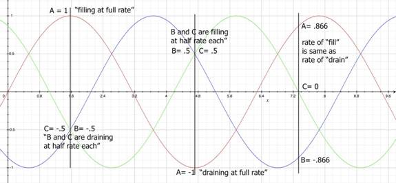
You can see on the graphic that no matter where you are in time (represented by a vertical line cutting through all three phases), the rates of “fill” and “drain” equal each other. You can view the currents as complimentary.
Now, add the condition that the level in the tank must stay exactly the same. This necessitates all currents to be equal. If the currents are not equal, the level in the tank will change. In order to account for this, connect a fourth hose to the tank and call it neutral. The fluid imbalance will flow in the neutral hose.
Now, imagine two tanks. Hoses A and B are connected to the first tank and Hose C is connected to the second tank. There is a neutral hose between tanks and back to the source. If A, B, and C all have the same volume, then the rates of fill and drain are again the same. In this case there will be current flow back and forth between the tanks, but no current flow in the neutral hose back to the source. In the case where there is a slight imbalance, there will be equalization flow between the tanks and a small imbalance flow back to the source.
As for how the current from two phases results in a neutral that is the equivalent of one phase, look at this:
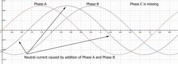
The addition of Phase A current, Red, and Phase B current, Blue, results in an equivalent (time-shifted) sinusoid (black).
Looking at the graph a little more closely, you will notice that the imbalance sinusoid (black) is exactly opposite that of the missing Phase C sinusoid. Therefore, when the Phase C sinusoid is added, the imbalance sinusoid goes to zero.
Eric Stromberg, P.E.
Stromberg Engineering, Inc.
www.strombergengineering.com
eric@strombergengineering.com


 Send to a Friend