|
2011 Changes to the NEC – 200.6
The following is an instructional page from our 2011 Changes to the NEC Textbook/DVD Package complete with graphics and video where applicable. As part of our on-going effort to provide free resources to help the industry, we will be sending this content as part of a series of newsletters. Each newsletter will feature pages taken directly from our textbooks. This can be a great training resource for your organization!
There are some important features in this text which help to highlight the changes that you should be aware of:
- Each Code section which contains a change includes a summary of the change, followed by a paraphrase of the NEC text affected by the change. Any specific change is denoted by underlined text and in the corresponding chapter color
- Graphics with green borders and 2011 CC icons next to the heading are graphics that contain a 2011 change; graphics without a green border or icon are graphics that support the concept being discussed, but nothing in the graphic was affected by a 2011 Code change.
2011 Changes to the NEC Part 1 |
200.6 Means of Identifying Grounded Conductors
This section has been reorganized into a list format.
200.6 Neutral Conductor Identification.
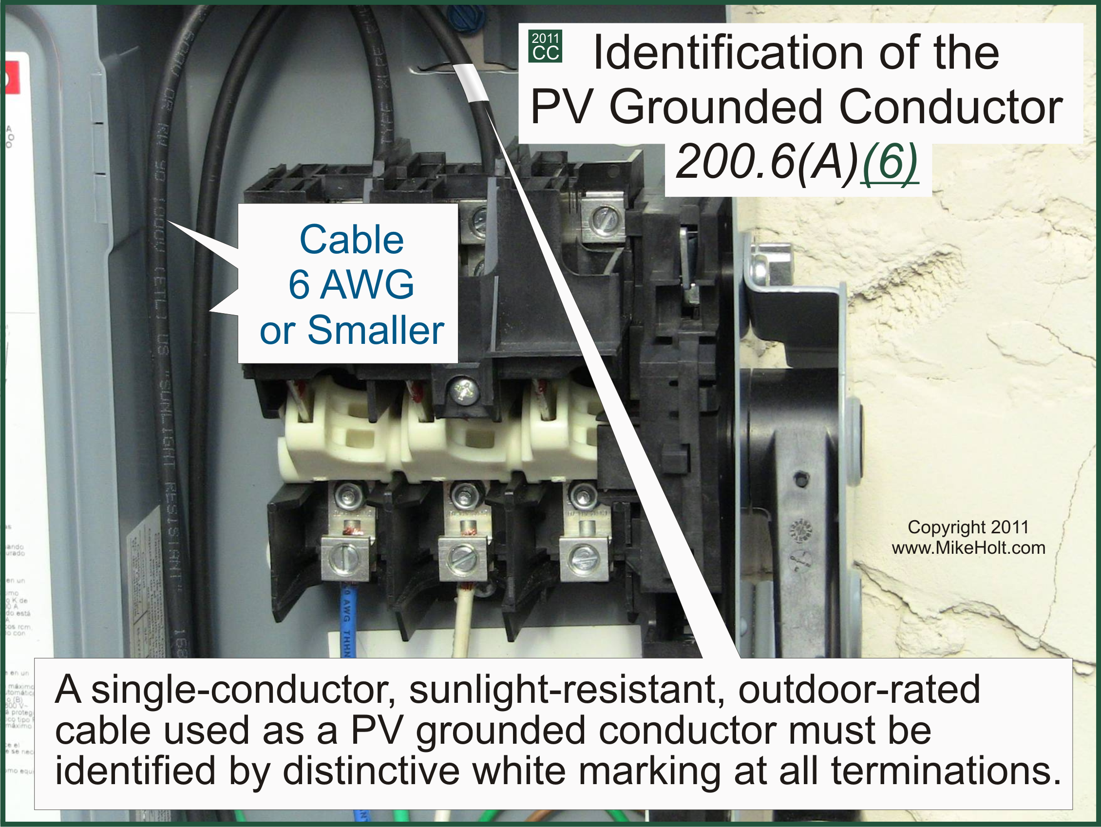
(A) 6 AWG or Smaller. Neutral conductors 6 AWG and smaller must be identified by one of the following means:
Figure 200-4 (Click on image to enlarge)
(1) By a continuous white outer finish.
(2) By a continuous gray outer finish.
(3) By three continuous white stripes along its entire length on other than green insulation.
(4) Wires that have their outer covering finished to show a white or gray color but have colored tracer threads in the braid identifying the source of manufacture are considered to meet the provisions of this section.
Author’s Comment: The use of white tape, paint, or other methods of identification isn’t permitted for neutral conductors 6 AWG or smaller.
(6) A single-conductor, sunlight-resistant, outdoor-rated cable used as the neutral conductor in photovoltaic power systems as permitted by 690.31(B) can be identified by distinctive white marking at all terminations.
Figure 200-5 (Click on image to enlarge)
ANALYSIS: This section contains eight possible ways to identify the neutral conductor, yet the section was written in a paragraph format. The list format is easier to read, and is also easier to understand. Code users will likely appreciate this change. |
200.6(B) Sizes Larger Than 4 AWG
This section has been rewritten into a correct list format, and the term “larger than 6 AWG” has been changed.
200.6 Neutral Conductor Identification.
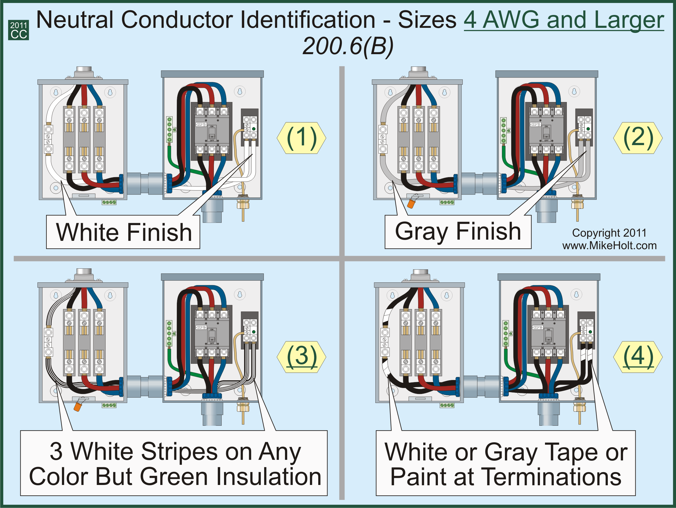
(B) Size 4 AWG or Larger. Neutral conductors 4 AWG or larger must be identified by one of the following means:
Figure 200-6 (Click on image to enlarge)
(1) A continuous white outer finish along its entire length.
(2) A continuous gray outer finish along its entire length.
(3) Three continuous white stripes along its length.
(4) White or gray tape or markings at the terminations.
ANALYSIS: Of the four methods allowed by this section to identify larger neutral conductors, only three of the methods were written in list format. This change provides uniformity in Section 200.6 by incorporating all methods of identification into lists.
This rule applies to any conductor that’s 4 AWG or larger. This change clarifies that fact, and it also makes for an easier requirement to understand. For whatever reason, most people tend to agree that “4 AWG and larger” is easier to understand and visualize than “larger than 6 AWG.” This change will be a welcome one for most NEC users. |
200.6(D) Neutral Conductors of Different Systems
The text of this requirement has been revised to correlate with the requirements for ungrounded conductors.
200.6 Neutral Conductor Identification.
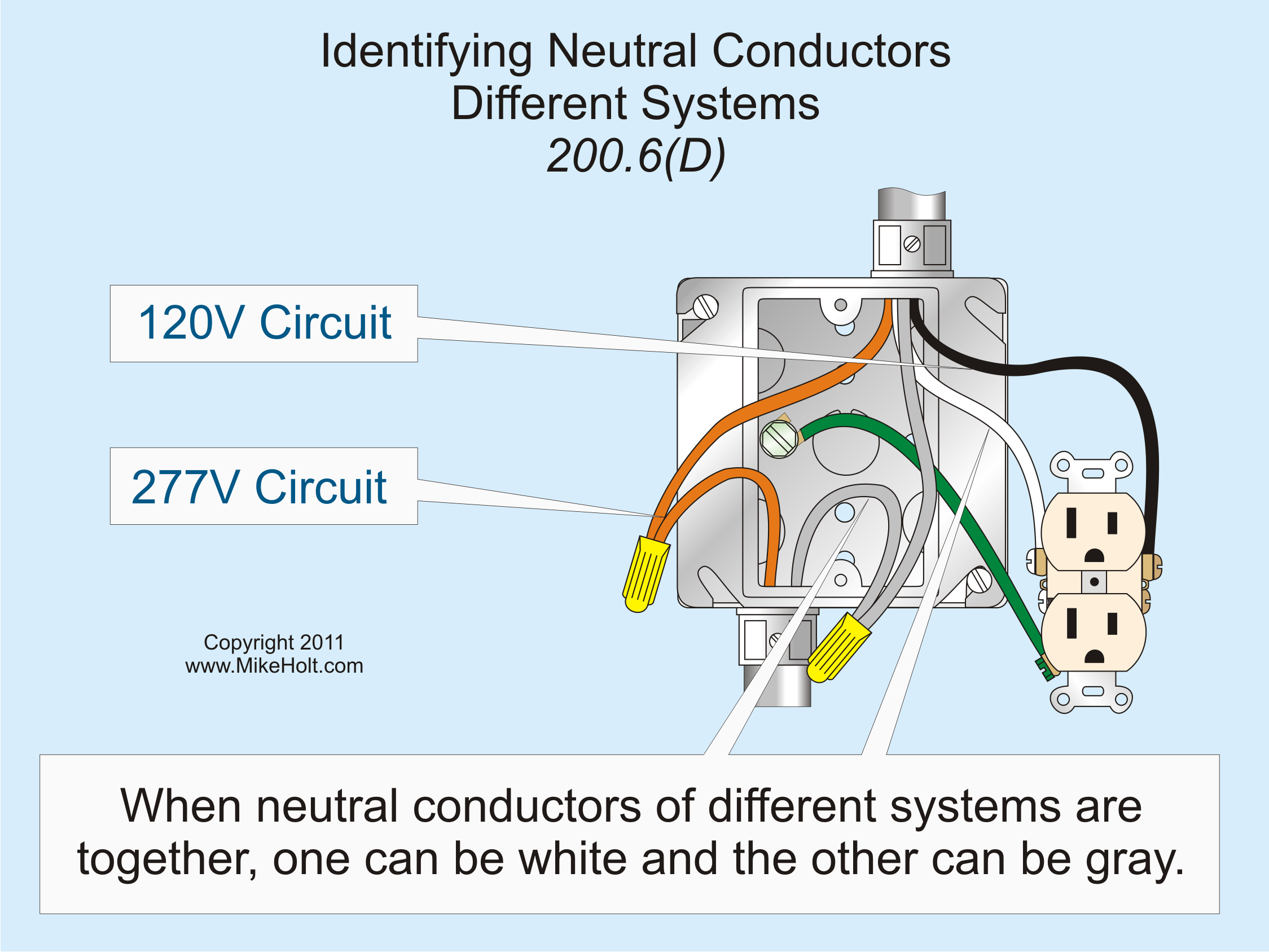
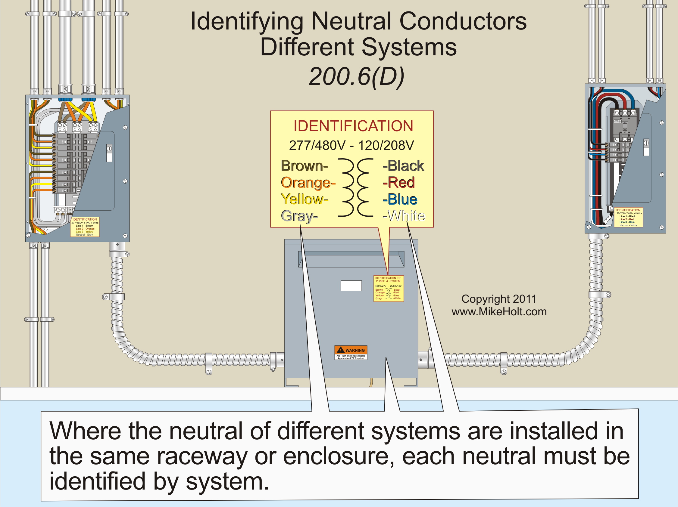
(D) Neutral Conductors of Different Systems. If neutral conductors of different voltage systems are installed in the same raceway, cable, or enclosure, each neutral conductor must be identified to distinguish the systems by:
(1) A continuous white or gray outer finish along its entire length.
Figure 200-7 (Click on image to enlarge)
(2) The neutral conductor of the other system must have a different outer covering of continuous white or gray outer finish along its entire length or by an outer covering of white or gray with a readily distinguishable color stripe (other than green) along its entire length.
Figure 200-8 (Click on image to enlarge)
(3) Other identification allowed by 200.6(A) or (B) that distinguishes the neutral conductor from other systems.
The means of identification must be documented in a manner that's readily available or be permanently posted where the conductors of different systems originate.
Figure 200-9 (Click on image to enlarge)
Author’s Comment: If a premises wiring system has circuits supplied from more than one voltage system, each ungrounded conductor must be identified by phase or line and system [210.5(C) and 215.12(C)].
ANALYSIS: 210.5(C) and 215.12(C) both have an allowance for documenting the identification scheme used “in a manner that’s readily available.” Because the identification of the neutral conductor will likely be at the same location as the documentation for the ungrounded conductors, it makes sense to have the same allowance for the neutral conductor. |
2011 NEC Changes DVD Package |
 |
Don't let the scale of the code changes intimidate you, this package will get you up to speed on the most essential 2011 NEC changes quickly. The book is well-organized, easy to follow, and the full-color illustrations bring the material to life. The DVDs bring together a group of experts from the field to discuss the changes and how they apply in the real-world.
This program includes the following items:
- Changes to the NEC 2011 Textbook
- Changes to the NEC 2011 DVD 1 & 2 includes Articles 90 - 810
Product Code: 11CCDVD
Price: $198.00
 |
|


