|
NEC Questions and Answers – Based on the 2011 NEC
April 2012
By Mike Holt for EC&M Magazine
Here’s the follow up to yesterday’s newsletter.This includes all of the answers to the questions sent, so you can see how you did.
Q1. Please explain the equipment temperature terminal rating for sizing conductors?
A1. Conductors are to be sized using their ampacity from the insulation temperature rating column of Table 310.15(B)(16) that corresponds to the lowest temperature rating of any terminal, device, or conductor of the circuit [110.14(C)(1)].
Unless the equipment is listed and marked otherwise, conductor sizing for equipment terminations must be based on Table 310.15(B)(16) in accordance with (a) or (b) [110.14(C)(1)]:
(a) Equipment Rated 100A or Less must be sized using these rules:
- Conductors must be sized using the 60°C temperature column of Table 310.15(B)(16).
- Conductors terminating on terminals rated 75°C are sized in accordance with the ampacities listed in the 75°C temperature column of Table 310.15(B)(16).
(b) Equipment Rated Over 100A must be sized using these rules:
- Conductors must be sized using the 75°C temperature column of Table 310.15(B)(16).
- Separate Connector Provisions. Conductors can be sized to the 90°C column of Table 310.15(B)(16) if the conductors and pressure connectors are rated at least 90°C.
Q2. What is the Code rule for marking of service equipment with available fault current?
A2. Service equipment in other than dwelling units must be legibly field-marked with the maximum available fault current, including the date the fault current calculation was performed and be of sufficient durability to withstand the environment involved [110.24(A)].
When modifications to the electrical installation affect the maximum available fault current at the service, the maximum available fault current must be recalculated to ensure the service equipment ratings are sufficient for the maximum available fault current at the line terminals of the equipment. The required field marking(s) in 110.24(A) must be adjusted to reflect the new level of maximum available fault current [110.24(B)].
Ex: Field markings aren’t required for industrial installations where conditions of maintenance and supervision ensure that only qualified persons service the equipment.
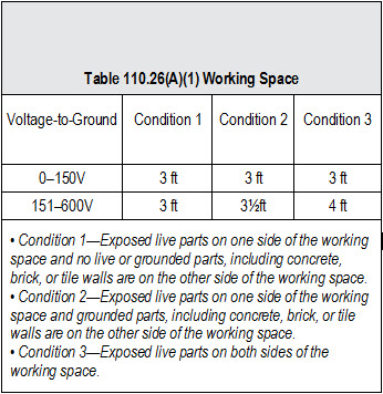
Q3. What are the working space requirements for equipment?
A3. For the purpose of safe operation and maintenance of equipment, access and working space must be provided about all electrical equipment [110.26].
Equipment that may need examination, adjustment, servicing, or maintenance while energized must have working space provided in accordance with (1), (2), and (3) [110.26(A)]:
Author’s Comment: The phrase “while energized” is the root of many debates. As always, check with the AHJ to see what equipment he or she believes needs a clear working space.
(1) Depth of Working Space. The working space, which is measured from the enclosure front, must not be less than the distances contained in Table 110.26(A)(1).
(a) Rear and Sides. Working space isn’t required for the back or sides of assemblies where all connections and all renewable or adjustable parts are accessible from the front.
(b) Low Voltage. If special permission is granted in accordance with 90.4, working space for equipment that operates at not more than 30V ac or 60V dc can be less than the distance in Table 110.26(A)(1).
Author’s Comment: See the definition of “Special Permission” in Article 100.
(c) Existing Buildings. If electrical equipment is being replaced, Condition 2 working space is permitted between dead-front switchboards, panelboards, or motor control centers located across the aisle from each other where conditions of maintenance and supervision ensure that written procedures have been adopted to prohibit equipment on both sides of the aisle from being open at the same time, and only authorized, qualified persons will service the installation.
Author’s Comment: The working space requirements of 110.26 don’t apply to equipment included in Chapter 8—Communications Circuits [90.3].
(2) Width of Working Space. The width of the working space must be a minimum of 30 in., but in no case less than the width of the equipment.
Author’s Comment: The width of the working space can be measured from left-to-right, from right-to-left, or simply centered on the equipment, and the working space can overlap the working space for other electrical equipment.
In all cases, the working space must be of sufficient width, depth, and height to permit all equipment doors to open 90 degrees.
(3) Height of Working Space (Headroom). The height of the working space in front of equipment must not be less than 6½ ft, measured from the grade, floor, platform, or the equipment height, whichever is greater.
Equipment such as raceways, cables, wireways, cabinets, panels, and so on, can be located above or below electrical equipment, but must not extend more than 6 in. into the equipment’s working space.
Ex 1: The minimum headroom requirement doesn’t apply to service equipment or panelboards rated 200A or less located in an existing dwelling unit.
Author’s Comment: See the definition of “Dwelling Unit” in Article 100.
Ex 2: Meters are permitted to extend beyond the other equipment.
Q4. What are the disconnect requirements for building or structure supplied by a feeder?
A4. A single disconnecting means for a building/structure must have an ampere rating not less than the calculated load as determined by Article 220. If the disconnecting means consists of more than one switch or circuit breaker, the combined ratings of the circuit breakers must not be less than the calculated load as determined by Article 220. In addition, the disconnecting means must not be rated lower than [225.39]:
- For installations consisting of a single branch circuit, the disconnecting means must have a rating of not less than 15A [225.39(A)].
- For installations consisting of two 2-wire branch circuits, the feeder disconnecting means must have a rating of not less than 30A [225.39(B)].
- For a one-family dwelling, the feeder disconnecting means must have a rating of not less than 100A, 3-wire [225.39(C)].
- For all other installations, the feeder or branch-circuit disconnecting means must have a rating of not less than 60A [225.39(D)].
Q5. Please explain the 10 ft feeder tap rule requirements?
A5. Except as permitted by 240.21 (A) through (H), overcurrent devices must be placed at the point where the branch circuit or feeder conductors receive their power. Taps and transformer secondary conductors aren’t permitted to supply another conductor (tapping a tap isn’t permitted) [240.21].
- Branch-circuit taps are permitted in accordance with 210.19 [240.21(A)].
- Conductors can be tapped to a feeder as specified in 240.21(B)(1) through (B)(5). The “next size up protection rule” of 240.4(B) is not permitted for tap conductors [240.21(B)].
Feeder tap conductors up to 10 ft long are permitted without overcurrent protection at the tap location if the tap conductors comply with the following [240.21(B)(1)]:
(1) The ampacity of the tap conductor must not be less than:
- The calculated load in accordance with Article 220 [240.21(B)(1)(1)(a)], and
- The rating of the device or overcurrent device supplied by the tap conductors [240.21(B)(1)(1)(b)].
(2) The tap conductors must not extend beyond the equipment they supply.
(3) The tap conductors are installed in a raceway if they leave the enclosure.
(4) If the tap conductors leave the enclosure or vault in which the tap is made, the tap conductors must have an ampacity not less than 1/10th of the rating of the overcurrent device that protects the feeder.
Note: See 408.36 for the overcurrent protection requirements for panelboards.
Example: A 400A breaker protects a set of 500 kcmil feeder conductors. There are three taps fed from the 500 kcmil feeders that supply disconnects with 200A, 150A, and 30A overcurrent devices. What are the minimum size conductors for these taps?
- 200A: 3/0 AWG is rated 200A at 75°, and is greater than 10 percent of the 400A overcurrent protection device (40A).
- 150A: 1/0 AWG is rated 150A at 75°, and is greater than 10 percent of the 400A overcurrent protection device (40A).
- 30A: 8 AWG is rated 50A at 75°, and is greater than 10 percent of the ampacity of the 400A overcurrent protection device (40A).
Anything smaller than 8 AWG can’t be used, as it will have an ampacity of less than 10 percent of 400A (40A) in the 75° column of 310.15(B)(16).
Q6. When installing a new electrical service in an existing building, does the Code require that the concrete be chipped up to access the rebar to establish a concrete encased electrode?
A6. Not according to the exception to 250.50. First off, the rule in 250.50 states that any grounding electrode described in 250.52(A)(1) through (A)(8) that’s present at a building/structure must be bonded together to form the grounding electrode system.
- Underground metal water pipe [250.52(A)(1)]
- Metal frame of the building/structure [250.52(A)(2)]
- Concrete-encased electrode [250.52(A)(3)]
- Ground ring [250.52(A)(4)]
- Ground rod [250.52(A)(5)]
- Other listed electrodes [250.52(A)(6)]
- Grounding plate [250.52(A)(7)]
- Metal underground systems, piping systems, or underground tanks [250.52(A)(8)].
Ex: Concrete-encased electrodes aren’t required for existing buildings or structures where the conductive steel reinforcing bars aren’t accessible without chipping up the concrete.
Author’s Comment: When a concrete-encased electrode is used at a building/structure that doesn’t have an underground metal water pipe electrode, no additional electrode is required.
Q7. What does the Code require in order to use a metal frame of a building as a grounding electrode?
A7. The metal frame of a building/structure can serve as a grounding electrode when it meets at least one of the following conditions [250.52(A)(2)]:
- At least one structural metal member is in direct contact with the earth for 10 ft or more, with or without concrete encasement [250.52(A)(2)(1)].
- The bolts securing the structural steel column are connected to a concrete-encased electrode [250.52(A)(3)] by welding, exothermic welding, steel tie wires, or other approved means [250.52(A)(2)(2)].
Q8. Does the Code allow metal piping for the interconnection of other grounding electrodes?
A8. Yes, Grounding electrode conductors and grounding electrode bonding jumpers are permitted to terminate to interior metal water piping located not more than 5 ft from the point of entrance to the building/structure [250.68(C)(1)].
Ex: In industrial, institutional, and commercial buildings where conditions of maintenance and supervision ensure only qualified persons service the installation, the entire length of the metal water piping system can be used for grounding purposes, provided the entire length, other than short sections passing through walls, floors, or ceilings, is exposed.
Q9. Does the Code allow metal cable tray systems to be installed in spaces used for environmental air (plenum)?
A9. Yes, metal cable tray systems can be installed to support the wiring methods and equipment which are permitted to be installed in this location [300.22(C)(2)(a)]
Q10. What is the Code rule regarding enclosures that contain splices, taps, and feed-through conductors?
A10. Cabinets, cutout boxes, and meter socket enclosures can be used for conductors as feeding through, spliced, or tapping off to other enclosures, switches, or overcurrent devices where all of the following conditions are met [312.8]:
- The total area of the conductors at any cross section doesn’t exceed 40 percent of the cross-sectional area of the space [312.8(A)].
- The total area of conductors, splices, and taps installed at any cross section doesn’t exceed 75 percent of the cross-sectional area of that space [312.8(B)].
- A warning label on the enclosure identifies the disconnecting means for feed-through conductors [312.8(C)].
Q11. What are the minimum bending radius requirements for Type NM and Type MC Cable?
A11. Bends in MC Cable must be made so that the cable won’t be damaged, and the radius of the curve of any bend at the inner edge of the cable must not be less than what’s described in each of the following instances:
- Smooth-sheath Type MC cables must not be bent so the bending radius of the inner edge of the cable is less than 10 times the external diameter of the metallic sheath for cable up to ¾ in. in external diameter [330.24(A)(1)].
- Interlocked- or corrugated-sheath Type MC cable must not be bent so the bending radius of the inner edge of the cable is less than seven times the external diameter of the cable [330.24(B)].
When Type NM Cable is bent, it must not be damaged and the radius of the curve of the inner edge of any bend must not be less than five times the diameter of the cable [334.24].
Q12. What is the rule on having a neutral conductor at light switch locations?
A12. Switches controlling line-to-neutral lighting loads must have a neutral provided at the switch location [404.2(C)].
Ex: The neutral conductor isn’t required at the switch location if:
(1) The conductors for switches enter the device box through a raceway that has sufficient cross-sectional area to accommodate a neutral conductor.
(2) Cable assemblies for switches enter the box through a framing cavity that’s open at the top or bottom on the same floor level, or switches enter the box through a wall, floor, or ceiling that’s unfinished on one side.
Note: The purpose of the neutral conductor is to complete a circuit path for electronic lighting control devices.
Q13. Where are tamper-resistant receptacles required?
A13. All nonlocking type 15A and 20A, 125V receptacles in the following areas of a dwelling unit [210.52] must be listed as tamper resistant [406.12].
- Wall Space—210.52(A)
- Small-Appliance Circuit—210.52(B)
- Countertop Space—210.52(C)
- Bathroom Area—210.52(D)
- Outdoors—210.52(E)
- Laundry Area—210.52(F)
- Garage and Outbuildings—210.52(G)
- Hallways—210.52(H)
Ex: Receptacles in the following locations aren’t required to be tamper-resistant:
(1) Receptacles located more than 5½ ft above the floor.
(2) Receptacles that are part of a luminaire or appliance.
(3) A receptacle located within dedicated space for an appliance that in normal use isn’t easily moved from one place to another.
(4) Nongrounding receptacles used for replacements as permitted in 406.4(D)(2)(a).
Nonlocking type 15A and 20A, 125V receptacles in guest rooms and guest suites must be listed as tamper resistant [406.13].
Nonlocking type 15A and 20A, 125V receptacles in child care facilities must be listed as tamper resistant [406.14].
For more NEC Practice purchase Mike Holt's NEC Practice Questions book, Based on the 2011 NEC.
|